Engineering Draftsmen: The Unsung Heroes of WWII
Bringing a museum exhibit to life to celebrate the contributions of the draftsmen of North American Aviation
My passion for the work of the engineering draftsmen who worked at North American Aviation during World War II culminated this summer in an exhibit I installed at the EAA Museum. You may ask yourself, why would anyone be interested in a museum exhibit about drafting? Although I could discuss the topic all day, I can boil it down to this:
The draftsmen and women of North American Aviation (NAA) toiled at desks during the war, but the work they were doing was of paramount importance. Without their design skills, artistic talent, and technical understanding, we would not have aircraft like the P-51 Mustang, T-6 Texan, B-25 Mitchell, T-28 Trojan, or P-82 Twin Mustang. These individuals were truly the first step in America’s air superiority during WWII.
Every aircraft manufacturer during WWII employed thousands of engineers to create the drawings that were used to fabricate parts and assemble aircraft on the factory floor. As a whole their contributions should not go unnoticed, but the focus of my exhibit was specifically the men and women engineers of North American Aviation.
Why just North American Aviation?
Well, the story starts with one man: Ken Jungeberg.
Ken’s first job out of college was as a draftsman (or engineer,
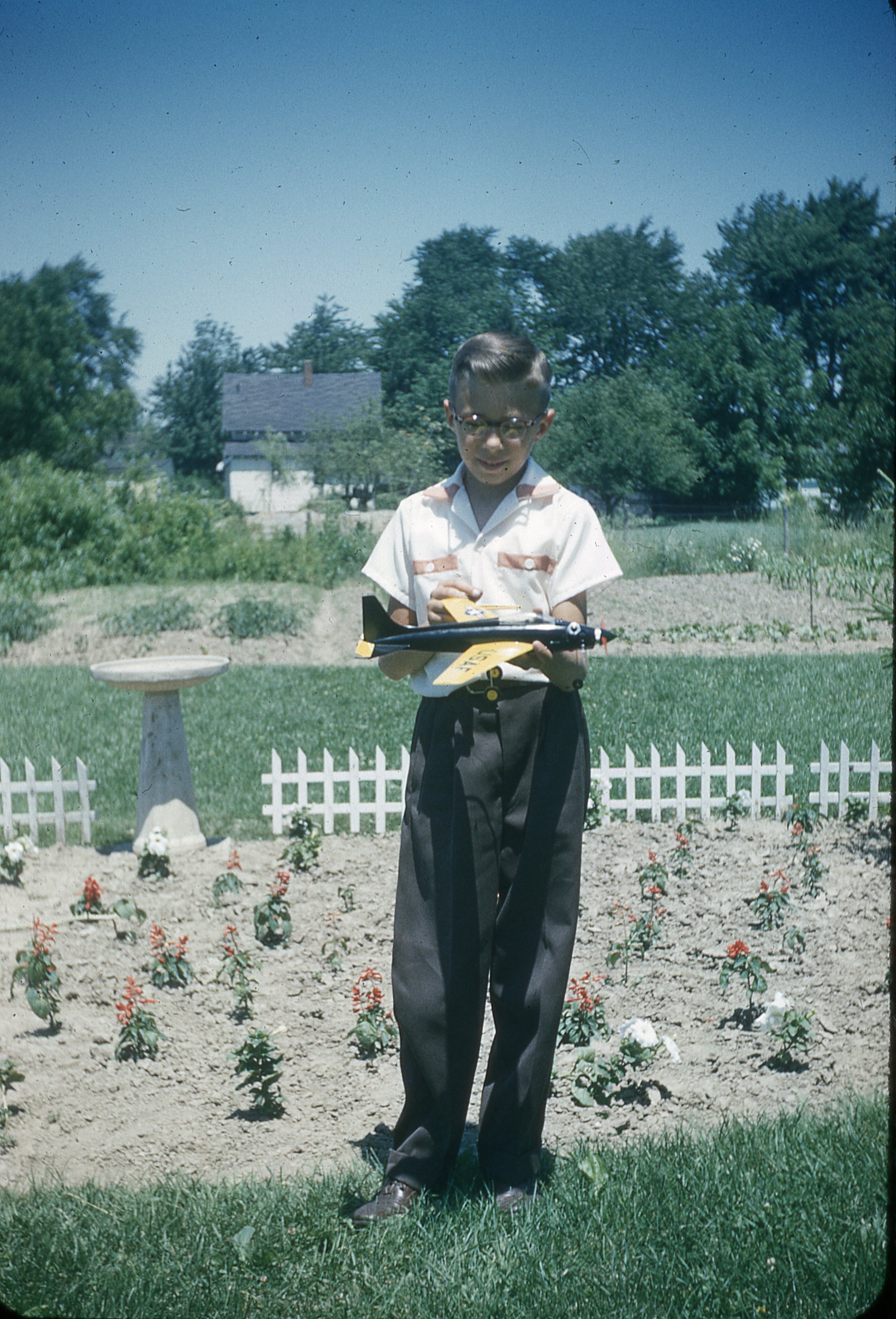 these terms are used interchangeably) for NAA in Columbus Ohio. Ken started at the drafting table in 1969, and worked in several engineering positions until the factory closed its doors in 1988. Because of his engineering background, Ken had a healthy appreciation for creating drawings by hand with pencil and eraser, although he was one of the first employees at Columbus to learn and use a CAD program. Ken had also harbored a passion for WWII aircraft from the time he was 2 years old - when his earliest childhood memory revolved around seeing a P-51 fly in the 1949 Cleveland Air Races.
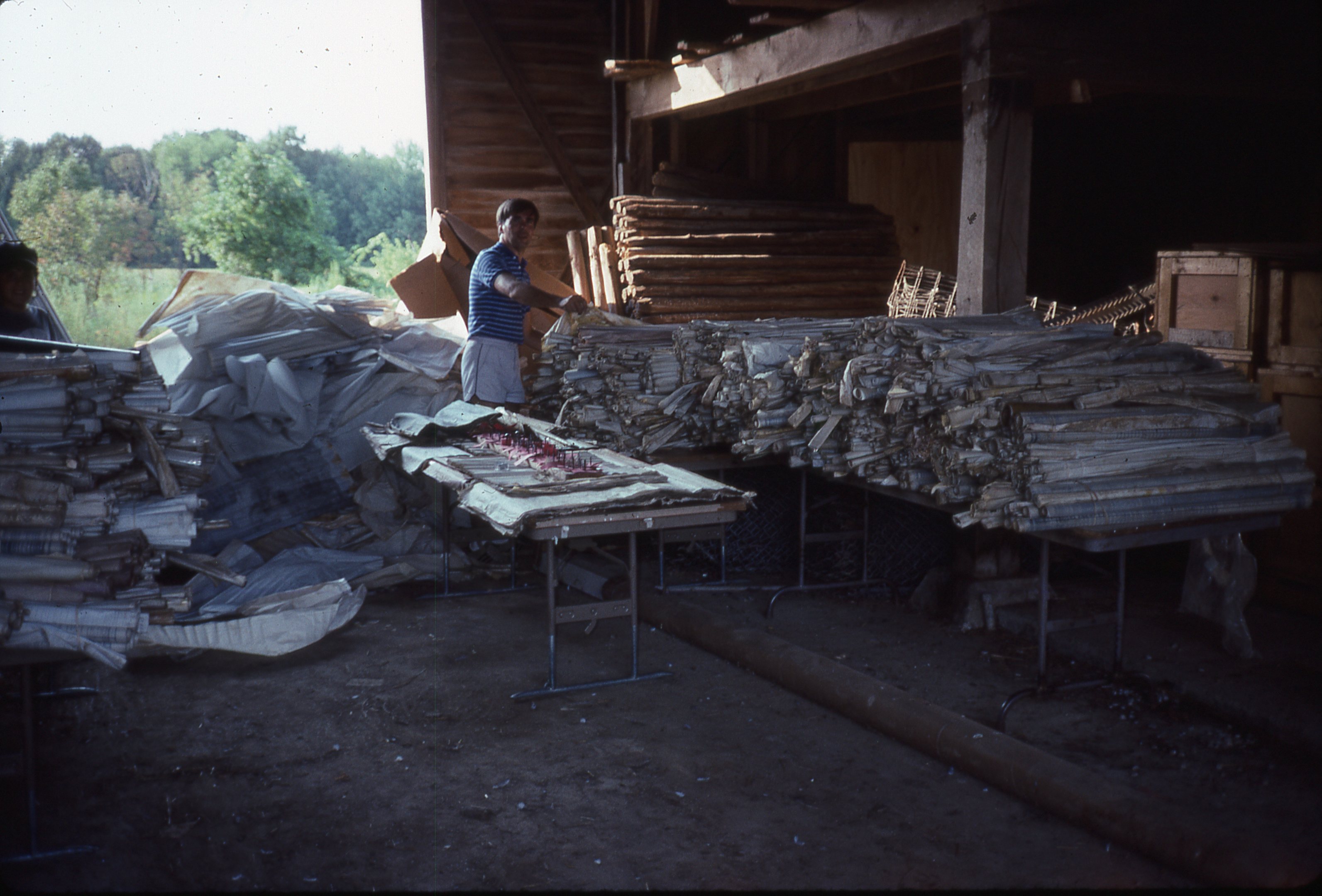
In 1988 as Ken was planning for a new position in Los Angeles, he heard a rumor that all of the WWII era drawings held in the engineering vault in Columbus were going to be thrown into the incinerator. Astonished, Ken thought he ought to do something to save this piece of history, but his attempts were unsuccessful at first. In what would have otherwise been a tragedy, the room where the drawings were being stored flooded and thousands of engineering drawings for the P-51, B-25, and T-6 were soaked through. Now unable to burn the wet drawings, factory officials notified Ken and relayed that he was approved to take them into his care.
After drying the drawings and repacking them, Ken stored them in his hangar and the basement of his home for 31 years. For more details and photos on Ken’s incredible story, see my other blog post titled “The Ken Jungeberg Collection” or read on to view the video.
It wasn’t until 2018 that I heard about Ken and his drawings through a contact at the Tri-State Warbird Museum in Batavia, OH. After an incredibly nerdy initial conversation surrounding the NAA part numbering system used to categorize engineering drawings, Ken agreed to send me several drawings to illustrate what he had. From that point on Ken and I talked regularly and eventually agreed that AirCorps Aviation would be the new home for the drawings that Ken had saved. As the transition was made, we decided to call the massive haul the Ken Jungeberg Collection to honor Ken’s legacy of preservation.
Cataloging & Organization
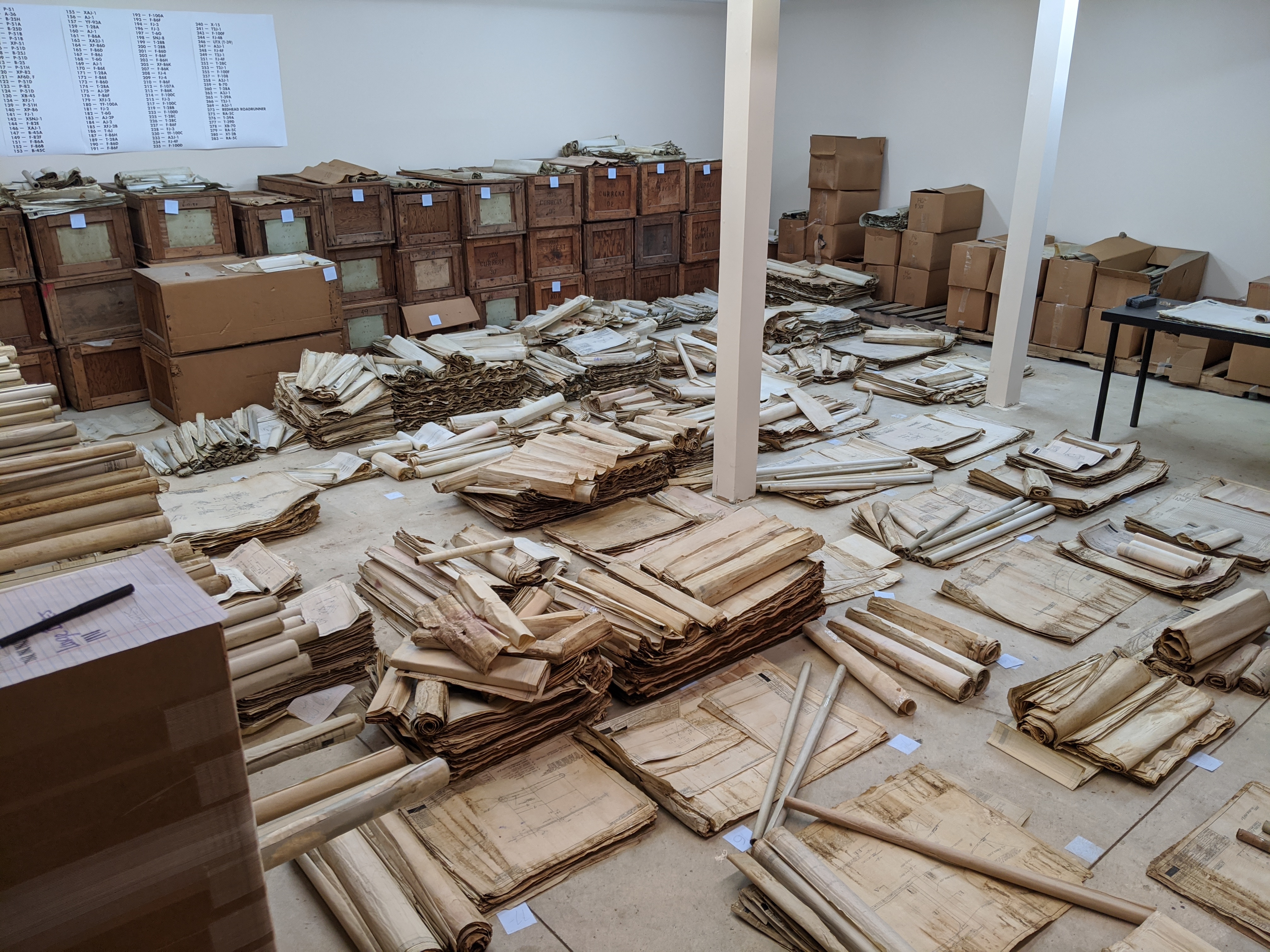
Fast forward several years - as I was sorting through what turned out to be approximately 50,000 drawings, an idea began to take shape. As I organized the drawings, I was cataloging details like the part number, description, date it was drawn, condition, material, and of course the draftsman who created it.
A draftsman would sign each drawing he/she did, most often with just a last name. However, if the last name was a common one, they would then add their first initial, and in very rare cases sign their entire name. As I waded through the drawings I began to see certain names over and over again. As I held the drawings in my hand I began to wonder… who were these draftsmen? How did they come to work at NAA? Did they know how important their work was? And of course, are any of them still alive today?
How to Honor the Story?
As I began doing research to locate any living draftsmen or their family members, the idea for a museum exhibit was rolling around in my mind. What better way to tell the story of these men and women, and use original drawings from the Ken Jungeberg Collection to highlight their work! While the majority of the engineering drawings were incredibly complex and technical, there was an undeniable aspect of artistic talent that is easy to appreciate when they are viewed in person.
Most people who interact with engineering data from WWII do so on microfilm. This format is how drawings were distributed during the war, and many people (including myself prior to working on Ken’s Collection) have never seen an original drawing. For more on microfilm and the frustrations that go along with it, see my blog called “Understanding WWII Era Microfilm”.
Seeing an original drawing is an exciting experience and one that I wanted to share with the general public. As I mulled this over, a theme emerged. I realized that many young people today might not know what drafting is, or the tools it required. With modern CAD programs like SolidWorks, AutoCAD, SolidEdge, and many more, engineering has become a job where the calculations and skills of drawing straight lines and perfect curves are left to a computer. So, I made the decision to center the exhibit around the basics of what a draftsman did, why it was important work, and how they actually went about creating a drawing.
The EAA Aviation Museum: A Gracious Host
The proximity of the EAA Museum in Oshkosh, WI to AirCorps Aviation’s main shop in Bemidji, MN, and their incredible collection, made them the logical choice for an exhibit of this nature to start. They were excited from the onset for an exhibit that highlighted a little known topic of the war effort. Working with Museum Director Chris Henry, and Curator Amelia Anderson, we decided early on that this new exhibit would be located in their “Telling Gallery”, which can be found in their impressive Eagle Hangar, an area that celebrates the contribution of the Greatest Generation and houses their warbird collection.
Installing the exhibit required taking into account one large work around - AirVenture. With an event that brought in over 677,000 attendees and 10,000+ aircraft in 2023, the months before AirVenture are packed with planning and logistics, so breezing in mid July to install a new exhibit was not an option! So at the end of May I drove a truckload of materials and 13 drawings cherry picked from Ken’s Collection to Wisconsin, and Amelia and I set about installing the exhibit that I had been conceptualizing for two years, now officially titled “Drafting: The Art of Aircraft Engineering in WWII”.
From 2D to 3D - An Exhibit Comes to Life
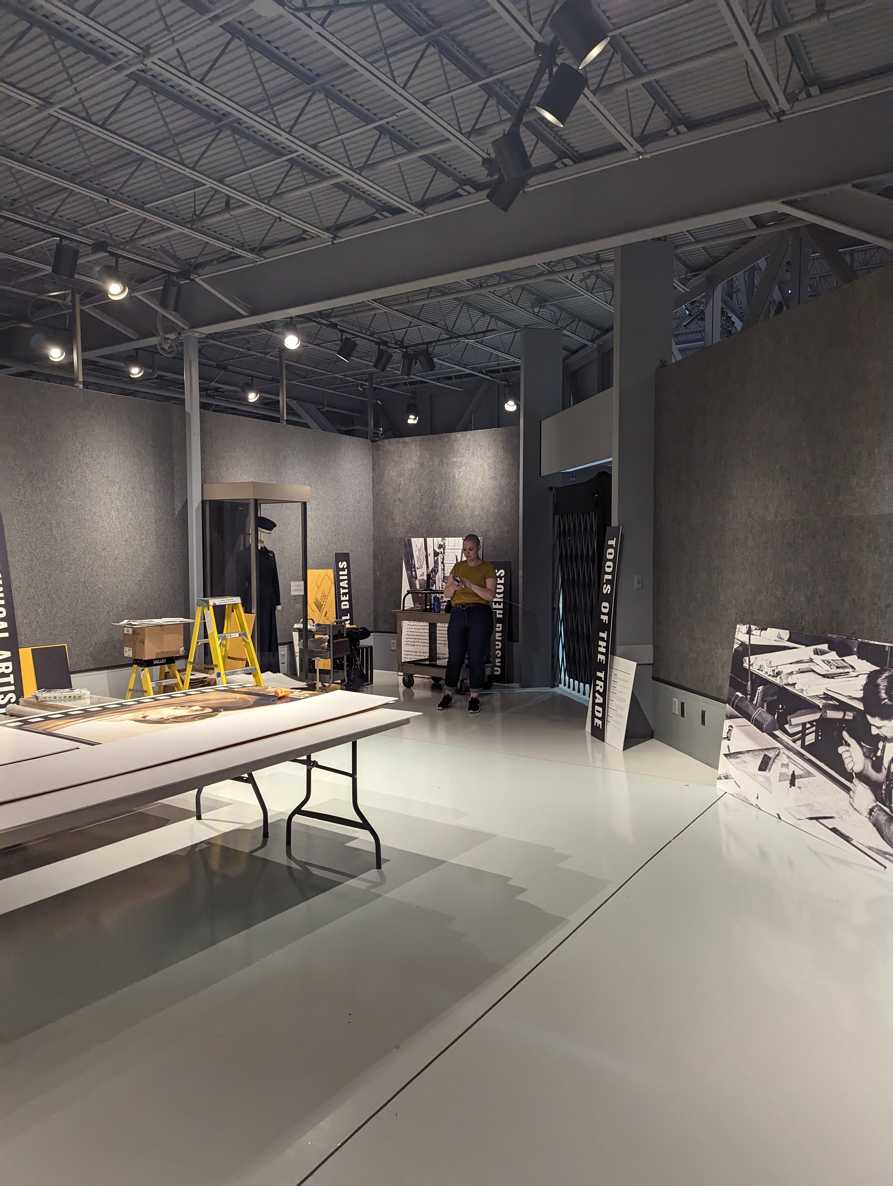
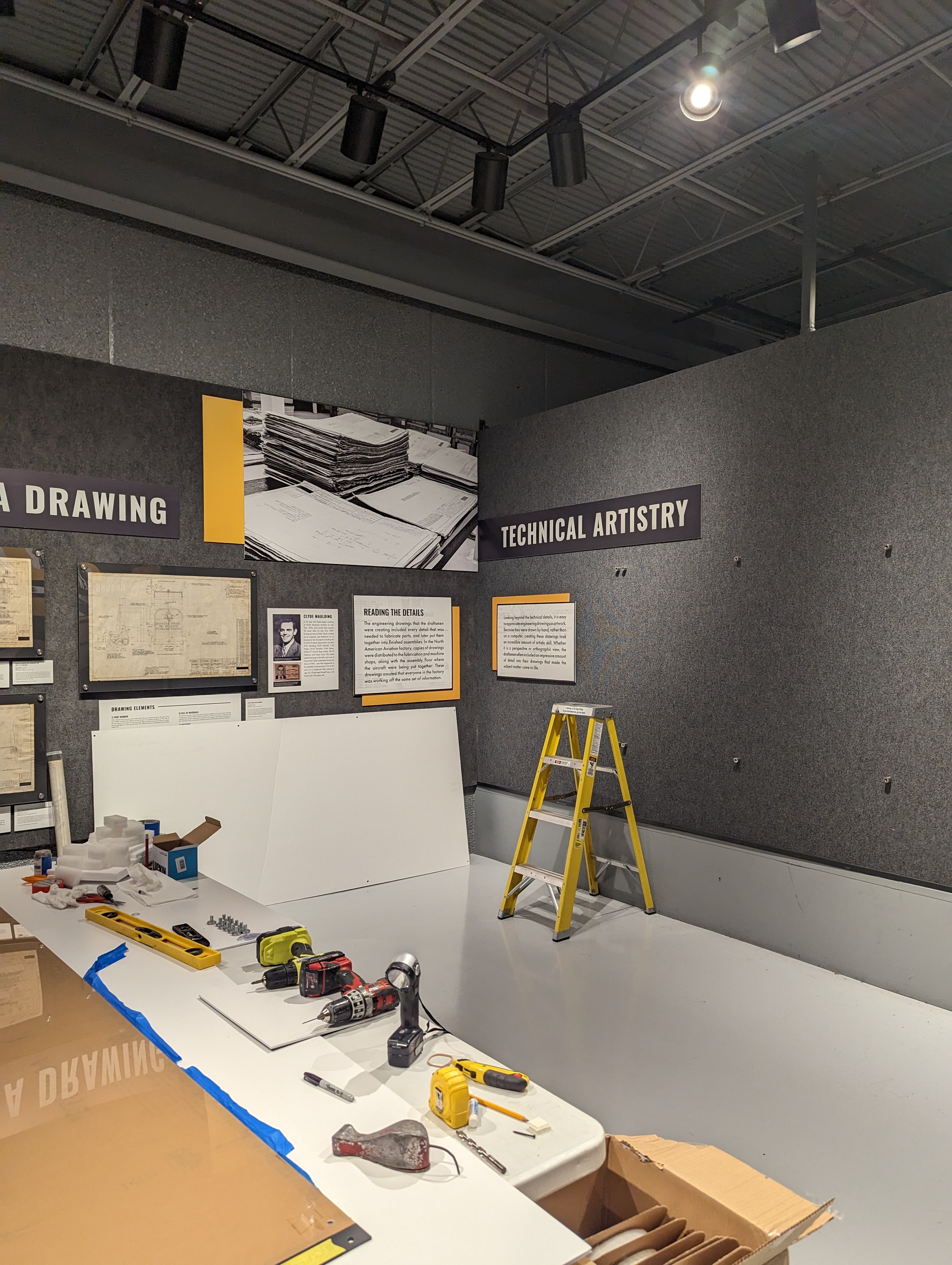
As Amelia and I stood in the empty Telling Gallery on installation day it was hard to imagine the finished exhibit. I had been thinking about it for so long, but being in the exhibit space meant that it was actually happening. We had everything we needed: large and small text panels, interactive elements, graphics and images, and of course all the materials to mount the drawings themselves.
Over the course of 4 long days we moved wall to wall hanging each element using a level and velcro strips to hold the text panels to the fabric covered walls. We encountered a few bumps along the way, but as things progressed the feeling was surreal. I had been looking at the design layouts on paper for months, so seeing them in 3 dimensions and full scale was incredible. Each wall presented its own challenges, but when we stepped back at the end of the week the feeling of accomplishment was palpable!
Telling the Story of the Draftsmen
The finished exhibit is broken down into seven sections, each focusing on a specific topic of the draftsmen’s work and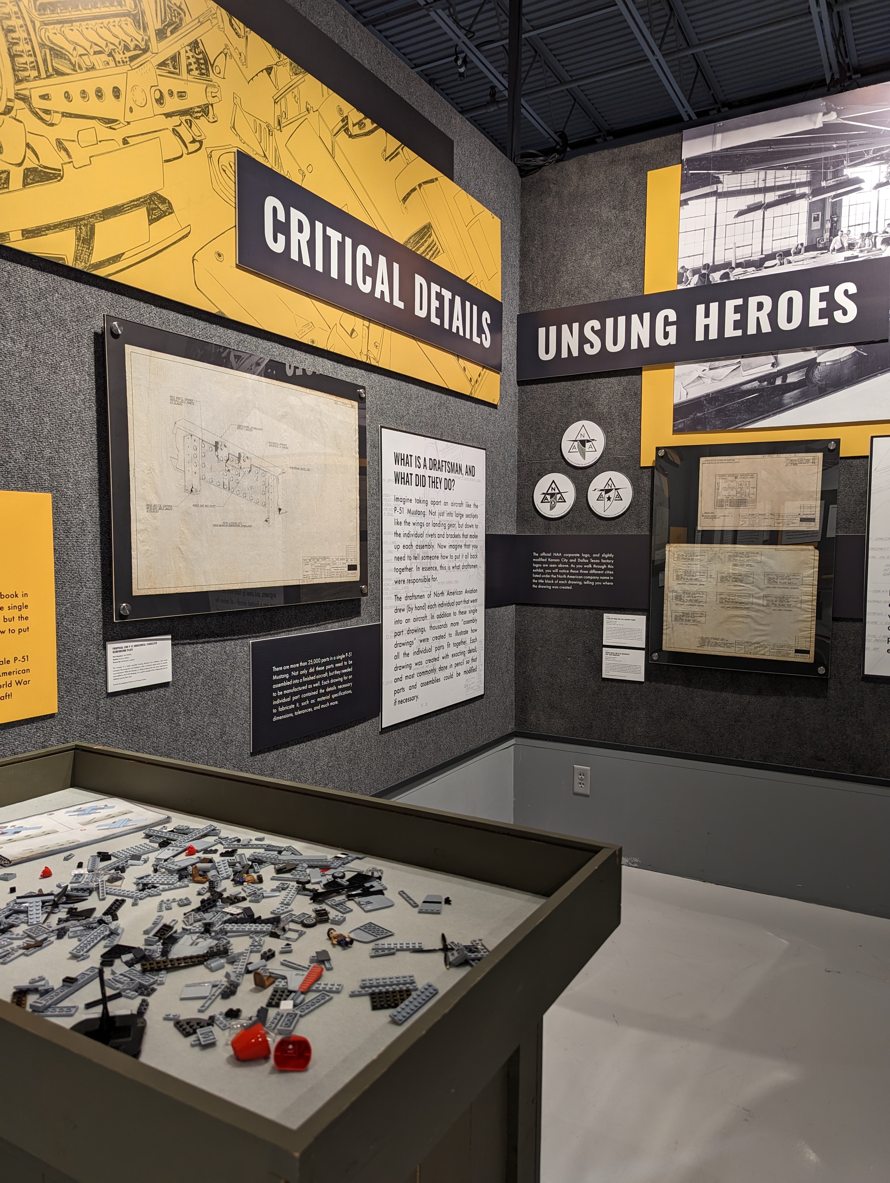 contribution to the war effort.
The introduction wall opens with a sentence that sums up the exhibit:
Draftsmen: They put pencil to paper and in doing so changed the course of WWII from behind a desk.
Using two original drawings, this section highlights the importance of the work the draftsmen were doing, and gives a brief overview of the three WWII era NAA factories, and the differences in their logo design!
Adjacent is a wall that features an interactive element - Legos! This wall, titled “Critical Details”, explains the work the draftsmen were doing using the analogy of an instruction book that comes with a Lego set. This area is designed to educate a younger visitor as to the purpose of an engineering drawing in a way that is easy to understand. Visitors are encouraged to use the supplied instruction book to build a Lego version of a P-51.
Technical Artistry
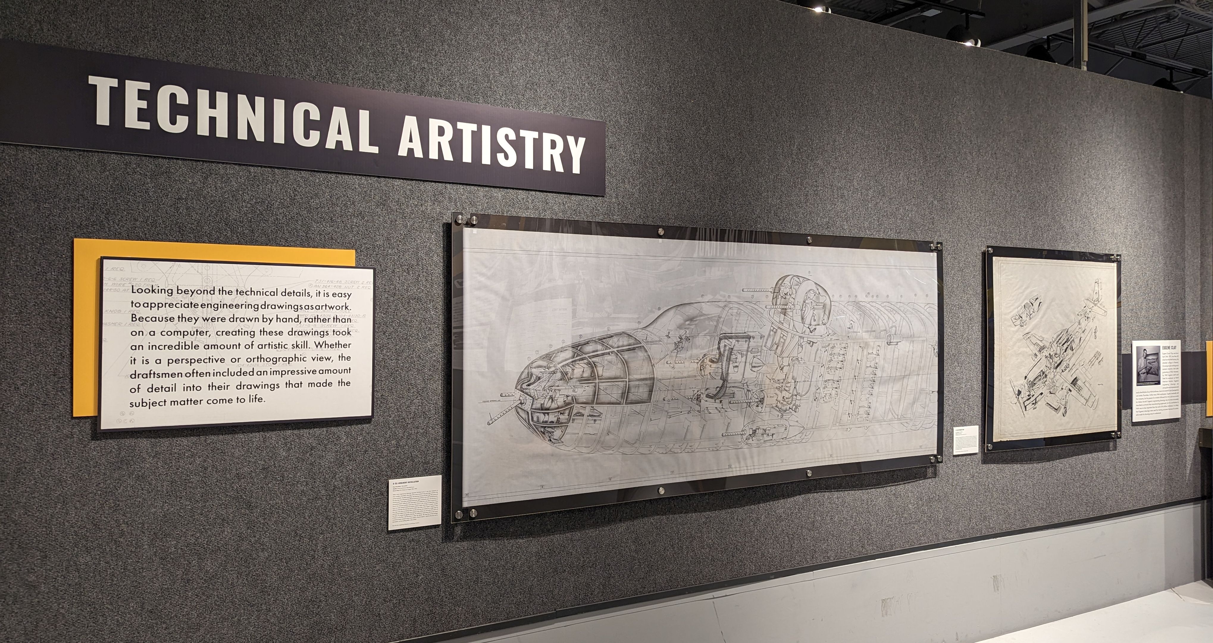
The largest wall of the exhibit features two drawings that can only be described as works of art. Visitors can scrutinize the incredible details present in a B-25 armament installation, and an exploded view of a P-51D. The 8 foot section of the B-25 drawing displays the nose gun and upper turret sections of the aircraft. This drawing was done using a combination of pencil and ink, and when rolled out fully measures 28 feet long!
The exploded view of the P-51D on this wall was drawn in the typical fashion, pencil on engineering vellum, and visitors who look closely can see slight smudges and eraser marks. A brief biography of the draftsman who created this drawing, Eugene Clay, can be found to the right - a connection I was able to make after substantial research. Eugene and many other draftsmen were the epitome of left and right brained individuals. They had the ability to understand the technical side of aircraft construction, and the artistic talent to accurately portray the information so others could understand it. This combination of skills is often why I use the term “technical artistry” to describe the draftsmen.
Let’s Get (Really) Technical!
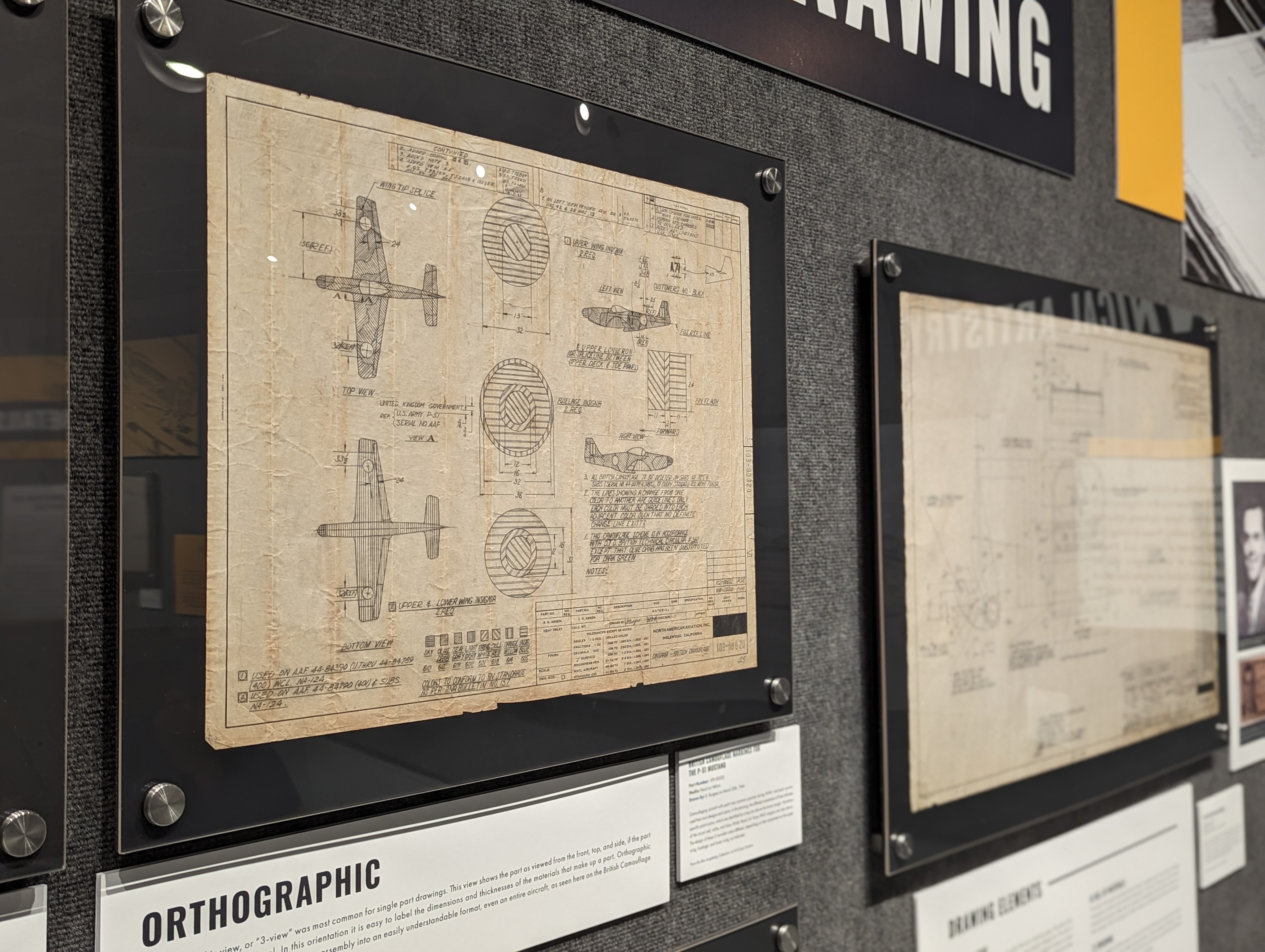
Perhaps the most technically complex section of the exhibit is an area that delves into exactly what information is contained on a drawing, and the different views that a draftsman used to depict a part or assembly in 2 or 3 dimensions. The first of the 5 drawings displayed on this wall is the iconic NAA brake/rudder pedal. This pedal was installed on almost every model of P-51, B-25, and T-6 that came off the factory line in WWII, no small feat!. Accompanying this drawing is an ode to the man who created it, Clyde Maulding. Clyde spent his entire career working for NAA, from 1936 to 1969, and kept a scrapbook that contained photographs and hand written notes describing the projects he worked on, in addition to his ID badge and other treasures. Clyde’s children were kind enough to share the scrapbook with me and allow me to use several of the photos it contained in the exhibit.
Next to Clyde’s drawing are four smaller drawings (D size, for all of you engineering nerds out there) that illustrate the differences between isometric, orthographic, oblique, and perspective views. Choosing the correct way to depict a part or assembly was a critical part of a draftsman’s job - choose the wrong one and a drawing could be confusing, or not contain the proper information! This area of the exhibit highlights the fact that draftsmen were able to visualize a part in three dimensions without having a physical example in front of them - a skill it can be argued that someone is born with, not taught.
Bringing the Ken Jungeberg Story to Life
Tucked into the corner of the exhibit is an area titled “Saved From The Inferno” aimed at telling Ken’s incredible story of saving the drawings in more detail. A 20 minute video captures Ken telling his story, with additions from myself and AirCorps Aviation’s general manager Erik Hokuf. The goal of the video is to highlight how Ken’s actions and willingness to take on the responsibility of caring for the drawings will affect the warbird community in perpetuity. Ken is truly an inspiration, and I feel honored to be the one to carry on his legacy of preservation, both with the exhibit and the continued work of cataloging his collection at AirCorps Aviation.
Connecting Drawings to People
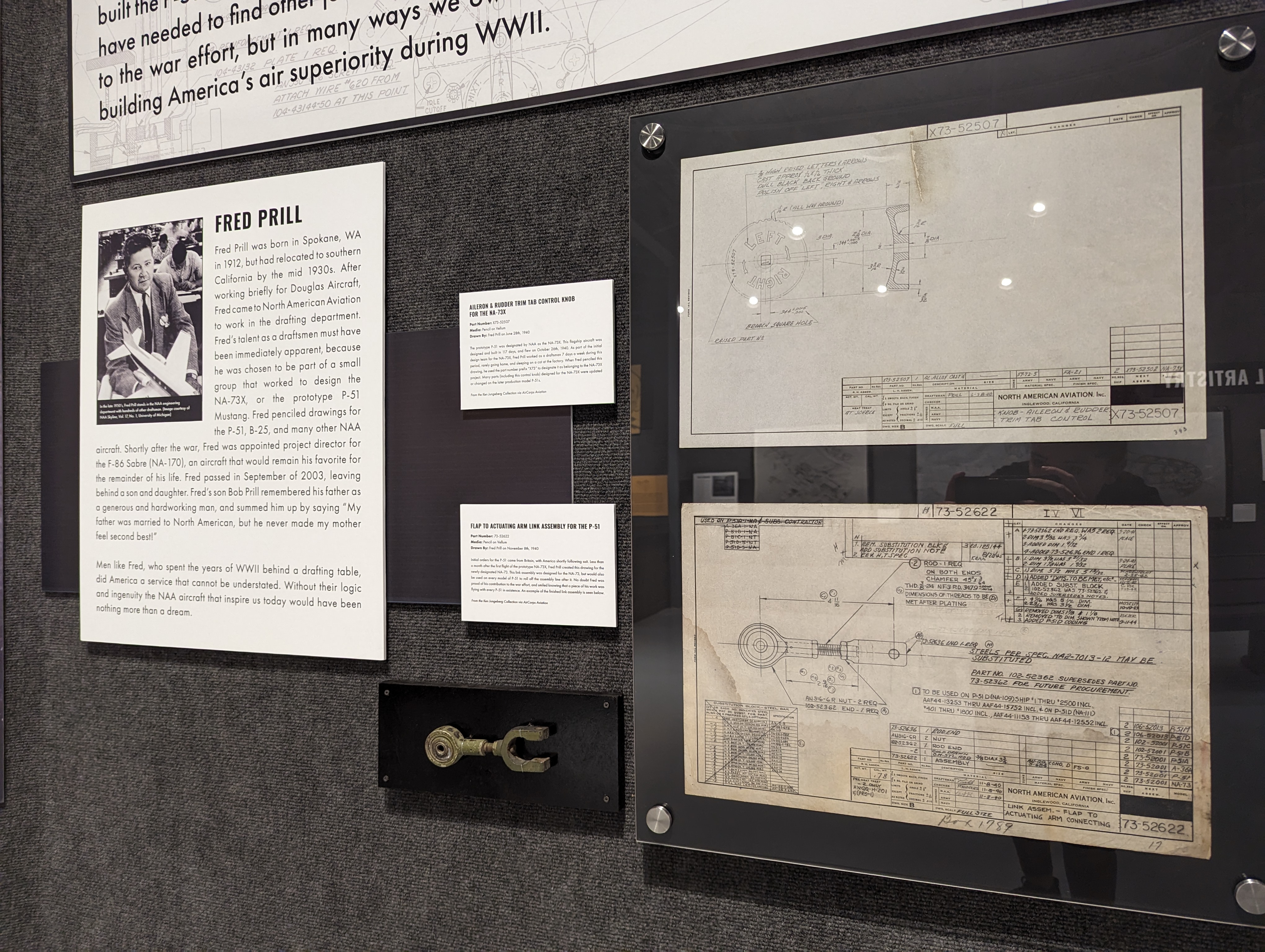
In my (admittedly biased) opinion, the key discussion piece surrounding the drawings in the Ken Jungeberg Collection is the draftsmen themselves, and the area titled “Making Connections” in the exhibit is dedicated to this. This area contains a biography of Fred Prill, the first draftsman who I was able to find information on. (For more on the single photograph that helped me begin locating the draftsmen, see my blog titled “The Draftsmen of NAA Inglewood”.) Fred is pictured next to two of his original drawings, the first, a link assembly for the P-51 flap actuating arm, next to a mounted example of the finished part.
The second drawing is unique because it was created during the initial design phase of the P-51. Fred was part of the hand selected design team who slept in the factory and worked in shifts to create the prototype NA-73X in just 117 days. The drawing depicts the aileron and rudder control knob, a design that would later be changed on the production P-51.
Both of Fred’s drawings are quite technical in nature, and small enough that they could be easily overshadowed by the larger more artistic drawings both in the exhibit and in the Ken Jungeberg Collection at large. However, making the connection between Fred as a person and seeing his photograph next to his drawings, brings a humanizing element to what would otherwise be cold hard engineering facts. In a discussion with Fred’s son Bob I was able to gather the details that are contained in Fred’s short biography on this wall, and Bob’s quote summed up what I imagine many of the draftsmen to have epitomized:
“My father was married to North American, but he never made my mom feel second best!”
-Bob Prill (son of Fred Prill)
How Did They Do It?
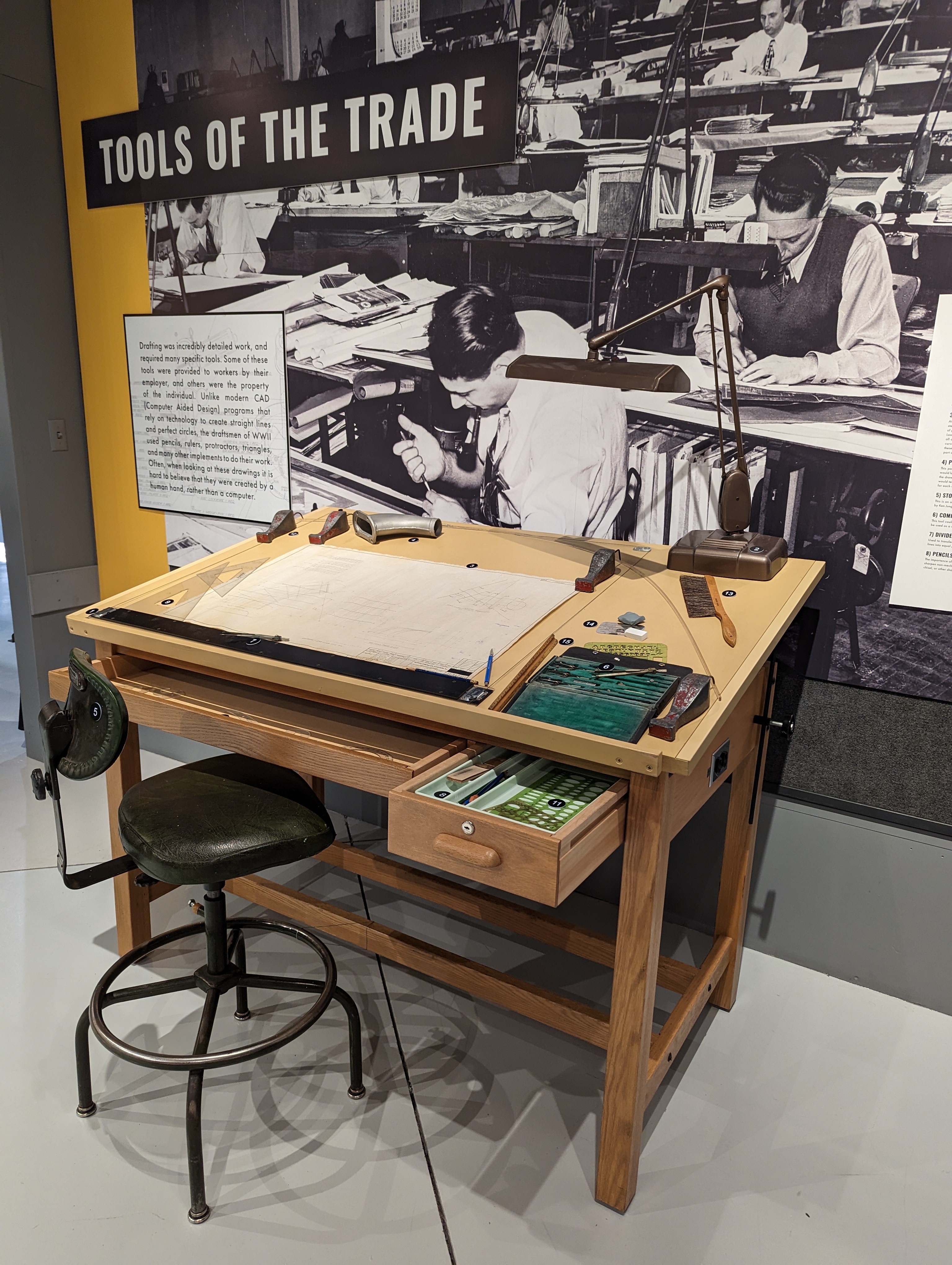
My personal favorite area of the exhibit is titled “Tools of the Trade” and focuses on the actual implements that the draftsmen used to do their work. In front of a life sized mural depicting a drafting room in 1942 sits a drafting table strewn with typical drafting tools. Many of these items came from Ken Jungeberg himself, including the drafting stool that he used during his years at NAA! A key defines the purpose of each item, and brings home the talent and precision it took to create engineering drawings in a time before computers.
Seeing the World Differently
It is my hope that this exhibit prompts visitors to look around them at everyday objects, and see not just a finished product, but the work that was put into each individual element - by an engineer. Even within the warbird community we tend to think of airplanes as a whole, rather than the tens and sometimes hundreds of thousands of parts that make them up. Each one of these parts had to be designed, tested, and finally fabricated before it could be installed on an aircraft, and an engineer was the first step in that process.
The drawings in this exhibit highlight how far we have come using technology in engineering, while demanding respect for the processes that the draftsmen and women used during WWII. Without their hard work and ingenuity hundreds of thousands of factory workers, pilots, and mechanics would have had nothing to build, fly, and tinker with.
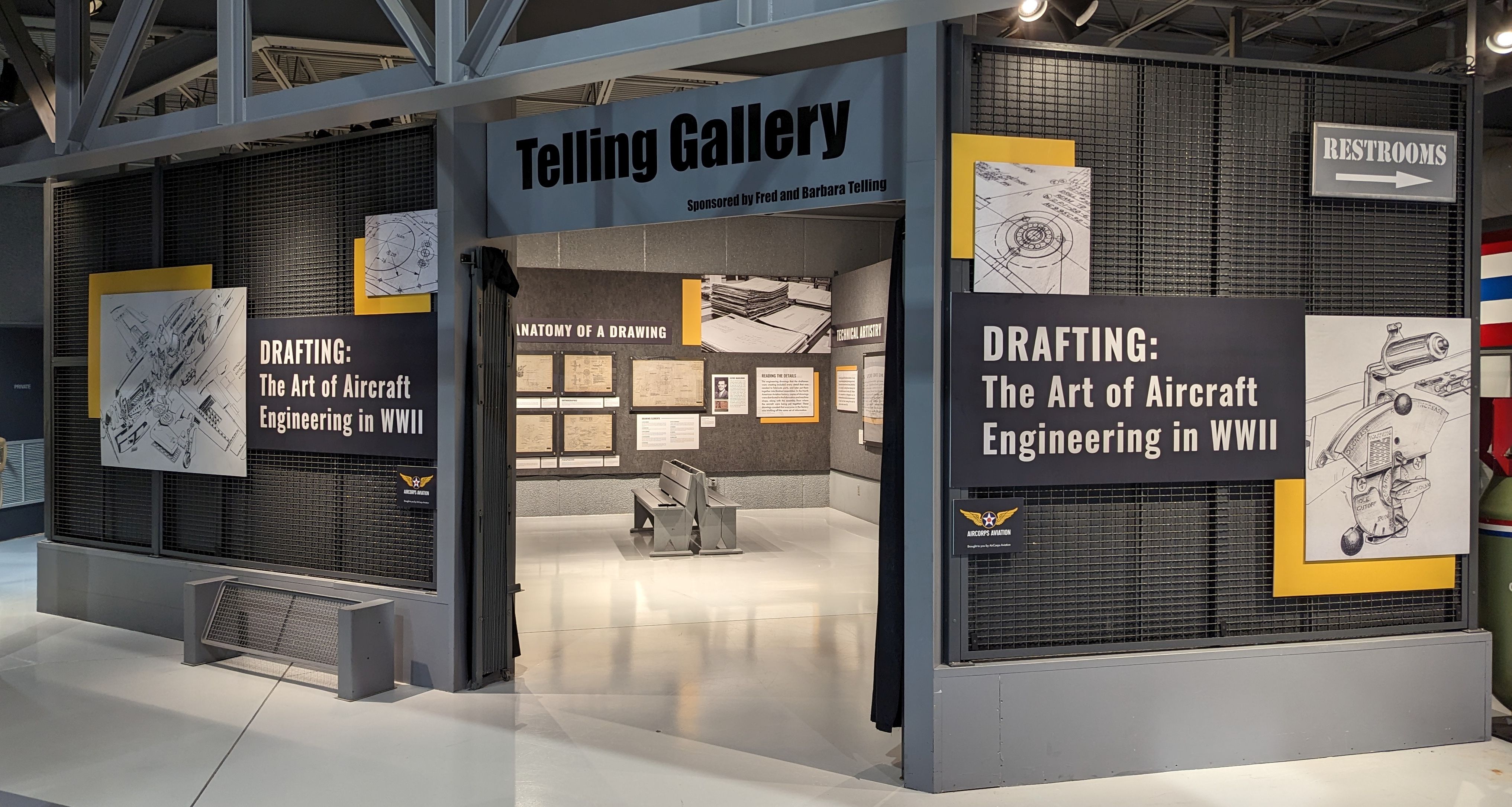
Exhibit Details
“Drafting: The Art Of Aircraft Engineering In World War II” will be on display at the EAA Museum until September of 2025. For more details on the exhibit location within the museum and visiting hours, please see the Featured Exhibits page on the EAA website.
For questions relating to the exhibit, please contact:
Ester Aube
Email: estera@aircorpsaviation.com
Phone: 218-444-4478
