How to use factory aircraft engineering drawings to create accurate scale models
It's A Small World After All
Since I was young I have been fascinated with miniatures of all kinds. As an adult, I have (so far) been able to resist the urge to spend all of my spare time and money building model trains, airplanes, or anything of the sort. Probably because I know myself well enough to know that once I got started, it would become an absolute obsession. But truth be told, I am jealous of those who build models in their spare time, and am continually impressed with the quality of work that is done in miniature.
So, why am I talking about scale models? Because, the AirCorps Library website is the place to go if your goal is to build a highly accurate warbird model! AirCorps Library is a website that offers members access to over 499,000 warbird engineering drawings, and thousands of warbird technical manuals.
AirCorps Library was originally created as a way for aircraft mechanics and restorers to get access to the engineering drawings they need to fabricate replacement parts, and actually build full scale flying aircraft. However, in the last year or so, the number of people who use the site to build scale models has overtaken the mechanic/operator crowd. This completely makes sense, because you don’t need to be a millionaire to build a scale model. Plus, it’s not uncommon for a model builder to spend as long building an aircraft at 1/32 scale, as we do at AirCorps Aviation building one full size!
Because of the increase in aircraft model builders using the AirCorps Library site, I wanted to write a blog specifically designed to explain the site, and how model builders can use it effectively.
How Detailed Do You Want To Go With Your Model?
The question that I answer most frequently for aircraft model builders is “Do you have what I need to build an accurate scale model?” The answer to this question is YES! If we can use the data to build an airworthy aircraft, then you can use it to create a model that is as accurate as your heart desires!
The engineering drawings that we make available to AirCorps Library members are original factory drawings. These drawings have been digitized from WWII era microfilm that came directly from the aircraft manufacturer. For more information on WWII aircraft microfilm and it’s positives and negatives check out my blog called “Understanding WWII Microfilm”.
In essence, every part of an aircraft (that was actually fabricated by an aircraft manufacturer) was included on the microfilm for that aircraft. This means that a set of engineering drawings for an aircraft can range anywhere from 784 drawings, for a small aircraft like the N3N Yellow Peril, to 27,000 drawings for a large aircraft like the B-17 Flying Fortress! Because there is a drawing for each individual part on an aircraft, (not to mention assembly drawings for how all those parts fit together) model builders can use this information to get as detailed with their build as they choose.

Getting Started - Choosing Aircraft Model
Engineering drawings are complex. Knowing how to decipher the information contained on the drawings is crucial to making sure that the components of your model fit together properly. Trying to utilize information from two drawings that pertain to different models of the same aircraft would be like trying to put together puzzle pieces that don’t fit. Because of this, it’s important to know exactly what model of aircraft you will be building before you get started. Most of the time when I talk to model builders this question has already been answered, but if it hasn’t - that’s the starting point. Each engineering drawing lists the specific model of aircraft that it pertains to, so as you work you can check that each drawing you are looking at is right for your project.
For example - knowing that you’d like to build a 1/32 scale P-51 Mustang is as far as you need to go, if you are going to head to your local hobby store to purchase a plastic kit off the shelf. However, if you are one of those people who craves a ridiculous level of accuracy, and also prefers to build your model more or less from scratch, then you need to determine if you want to build a P-51A, B, C, D, or H. Any warbird enthusiast can tell you that there are substantial structural and visual differences between these models. For example there are many elements that are required on a P-51A that would be irrelevant to someone building a P-51C.
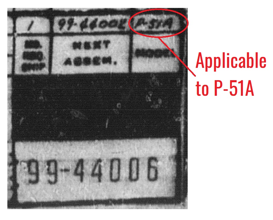
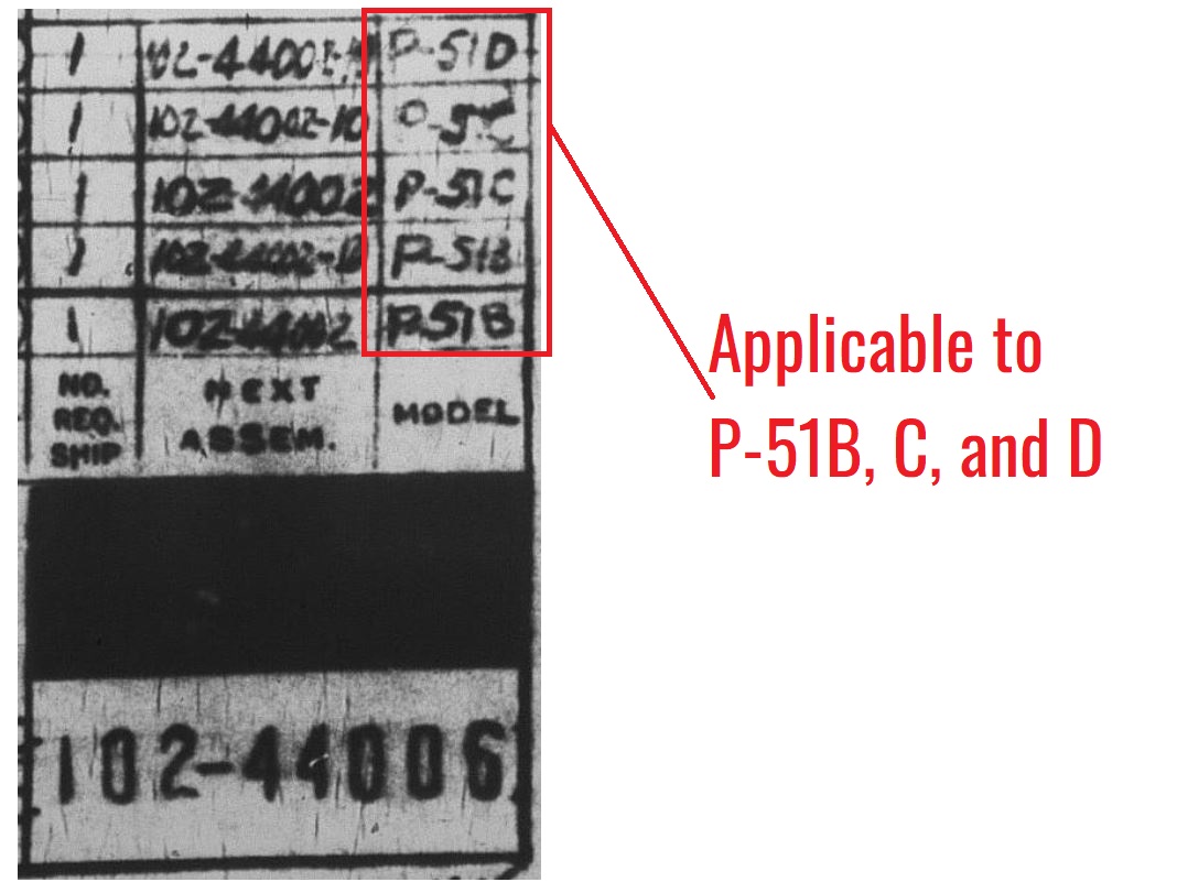
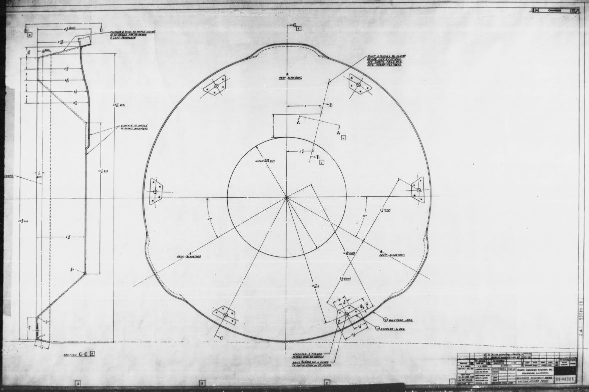
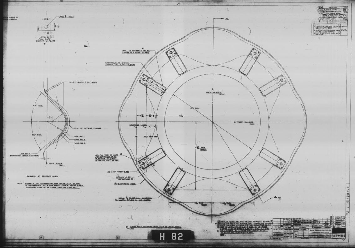
The two detail shots above both relate to exactly the same topic: they are of the bulkhead assembly for the rear section of the front spinner on the P-51. However drawing 99-44006 is specifically for the P-51A, while 102-44006 relates to later variants of the Mustang. The images below are more full examples of the same drawings, and the differences between the versions of the P-51 spinner can be seen more clearly.
Once you’ve settled on a specific model to build, then the real work can begin! The chart below details the microfilm that we currently have available to AirCorps Library members, along with the number of drawings in that set, and the specific models that the microfilm covers (if that information was provided by the manufacturer on the microfilm).
| Manufacturer & Aircraft | Specific Aircraft Models |
Number of Drawings Available Via AirCorps Library |
|
North American P-51 Mustang |
P-51A, P-51B, P-51C, P-51D, P-51H |
30,303 |
|
Republic P-47 Thunderbolt |
P-47B, P-47C, P-47D, P-47M |
20,270 |
|
Lockheed P-38 Lightning |
P-38E, P-38F, P-38G, P-38H, P-38J, P-38L, F-5A, F-5B |
20,534 |
|
Grumman F8F Bearcat |
F8F-1 |
3,206 |
|
Curtiss P-40 Warhawk |
N/A |
15,820 |
|
Grumman F6F Hellcat |
F6F-3, F6F-3N, F6F-5, F6F-5N |
8,169 |
|
Chance-Vought F4U Corsair |
F4U-1, F4U-1C, F4U-1D, F4U-4 |
43,805 |
|
Vickers/Supermarine Spitfire |
N/A |
2,998 |
|
Grumman F4F Wildcat |
FM-2 |
3,934 |
|
Bell P-39 Airacobra |
P-39A, P-39D, P-39F, P-39K, P-39L, P-39M, P-39N, P-39Q |
11,050 |
|
North American B-25 Mitchell |
B-25C, B-25D, B-25G, B-25H, B-25J |
53,306 |
|
Grumman TBM Avenger |
TBM-3 |
4,493 |
|
Boeing B-17 Flying Fortress |
B-17A, B-17B, B-17C, B-17D, B-17E, B-17F, B-17G |
33,610 |
|
Douglas A-26 Invader |
A-26B |
12,289 |
|
North American T-6 Texan |
AT-6A, AT-6C, AT-6D, AT-6F, AT-6G, SNJ-3, SNJ-4, SNJ-5, SNJ-6 |
12,025 |
|
Grumman JRF Goose |
JRF-4, JRF-5, JRF-6B |
1,535 |
|
Grumman J2F Duck |
J2F-1, J2F-2, J2F-3, J2F-4, J2F-5, J2F-6 |
2,518 |
|
Vultee L-5 Sentinel |
N/A |
2,519 |
|
Vultee BT-13 Valiant |
BT-13, SNV-1, SNV-2 |
3,193 |
|
Beechcraft Model 18 |
C-45G |
5,231 |
|
North American T-28 Trojan |
T-28A, T-28B |
15,313 |
|
Naval Aircraft Factory N3N Yellow Peril |
N/A |
784 |
|
North American T-34 Mentor |
T-34A |
2,412 |
|
Boeing Stearman |
N2S-1, N2S-2, N2S-3, N2S-4, N2S-5 |
2,504 |
|
Douglas C-47 Skytrain |
C-47, C-47A, C-47B |
22,801 |
| Douglas DC-6 | N/A | 25,990 |
How To Use Drawings On The AirCorps Library Website
So now you know the total number of drawings we have available, but how can you get started using this information to build your aircraft model? To get the most out of the engineering drawings we have on the site, you need to have a basic understanding about how they were originally organized, and how you can search for what you need on AirCorps Library. At a high level, this basic understanding can be broken down into three categories: part numbering systems, reading a drawing, and parts catalogs.
1. Part Numbering Systems
Many WWII aircraft manufacturers had part numbering systems that they used to organize like drawings/systems together. Each engineering drawing on a set of microfilm is always designated by a part number. This applies to drawings of individual nuts and bolts, all the way through drawings for larger assemblies. If a manufacturer had a part numbering system you will notice similarities in the part number with relation to the area of the aircraft that part belongs to. For a great example, check out my blog on the North American part numbering system.
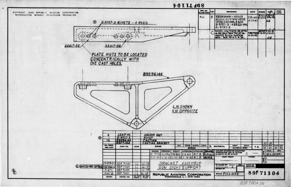
The two drawings below are both for the P-47 Thunderbolt. The drawing on the left (part # 89F71104) is a bracket assembly for the gunsight support, while the one on the right (part # 96F71110) is the full K14 gunsight installation. Because both of these drawings are related to armament, notice that the digit directly following the letter in each part number is a 7. In the Republic Aviation part numbering system, that 7 indicates that the drawing deals with some part of the armament installation for the P-47.
As a member of the AirCorps Library site you will notice that when you open the area for an aircraft there is a flowchart at the top of the page - this is what I call a “Drawing Tree”. This tree uses the manufacturer part numbering system to group like drawings together into buckets, so that similar drawings can be viewed together.
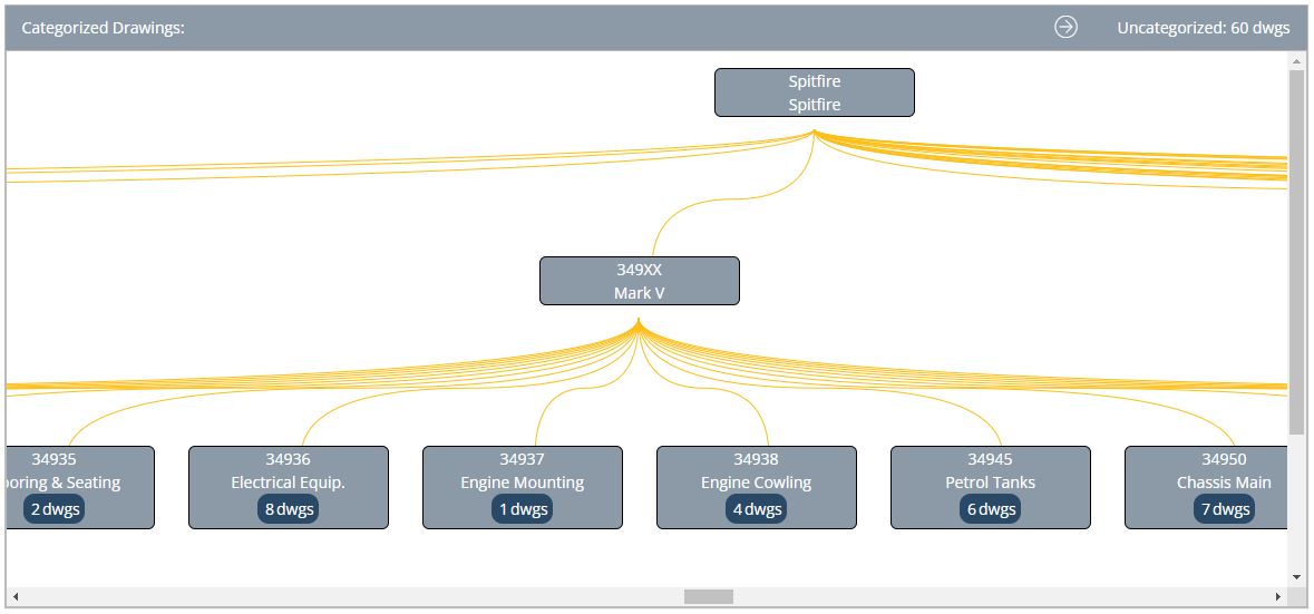
The drawing tree for the Spitfire can be seen above. Notice that each "bucket" is labeled with a topic. This means that the manufacturer had a discernable part numbering system.
Keep in mind that some manufacturers (think Douglas and Lockheed) did not have part numbering systems, so drawings are simply grouped together numerically and will not pertain to a specific topic. Don’t shoot the messenger here - I always find it hard to wrap my head around the fact that these manufacturers were able to keep their drawings organized when the part number for a spring can be numerically next to an engine installation!
One of the most helpful (and unique) aspects of the AirCorps Library website is that each engineering drawing we make available on the site is identified first and foremost by its part number. So, if you know what drawing you are looking for, you can just search the part number and find it quickly! This is the best option to use when searching for a drawing that you have found via the parts catalog - more on that in a bit.
2. Reading Drawings
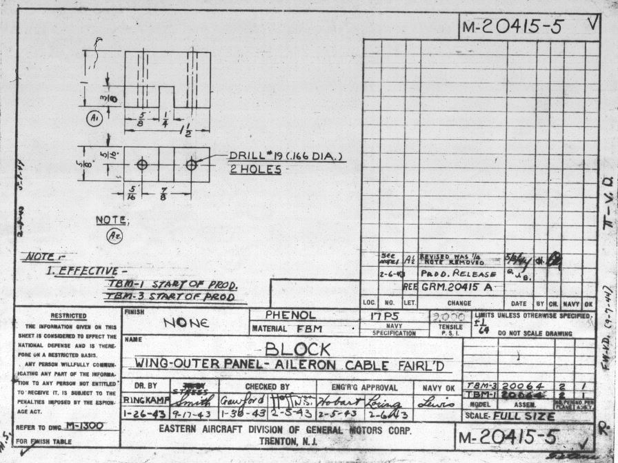
Most engineering drawings from WWII have a similar look. Part numbers are listed in the lower right corner, along with a description (or title) of what the part or assembly is. The title block also includes items like material specifications, heat treat information, finish specifications, and maybe most importantly, next assembly part numbers (more on this later). Additionally, the revisions (or changes) to a drawing can usually be found either attached to the title block, or in the upper right corner of the drawing.
Normally, dimensional data is the number one item that model builders are looking for when viewing drawings. Most of the time dimensions are found on the drawing that depicts an individual part, but occasionally dimensions can be found on an assembly drawing as well. For a more specific example of what is contained on a drawing, check out my short blog post called “Reading a Basic North American Part Drawing”.
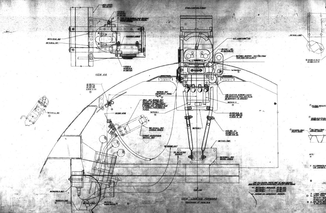
A basic dimensional drawing is shown below - part of the Grumman TBM microfilm.
3. Parts Catalogs
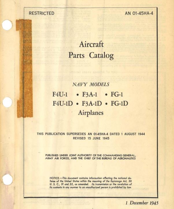
Knowledge of how to utilize an aircraft parts catalog is perhaps the single thing that will be the most helpful in a scale build. The parts catalog is also the second instance (besides the drawings themselves) where it is crucial to have a firm answer to the question of exactly what model of aircraft you are building. There are many different versions of an aircraft parts catalog, each one pertaining to different models of that aircraft, and referencing the correct one is key. With over 9,000 technical manuals on the AirCorps Library website, it’s likely that we have a version that will assist with most warbird models.
As you can see the parts catalogs below both relate to the Corsair, but each covers entirely different models.
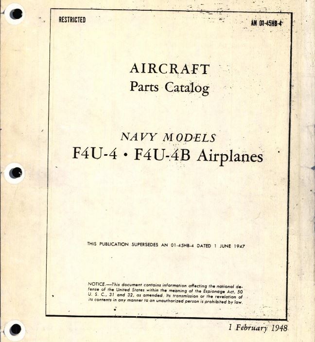
As a model builder, parts catalogs that were published after 1943 are the ones you should be looking for. The simple reason is that 1943 was the year that the illustrated parts catalog was implemented. Illustrated parts catalogs are broken into 2 main sections: the group assembly parts list, and the numerical parts list. Of these two, the group assembly parts list will likely be the most useful to model builders.
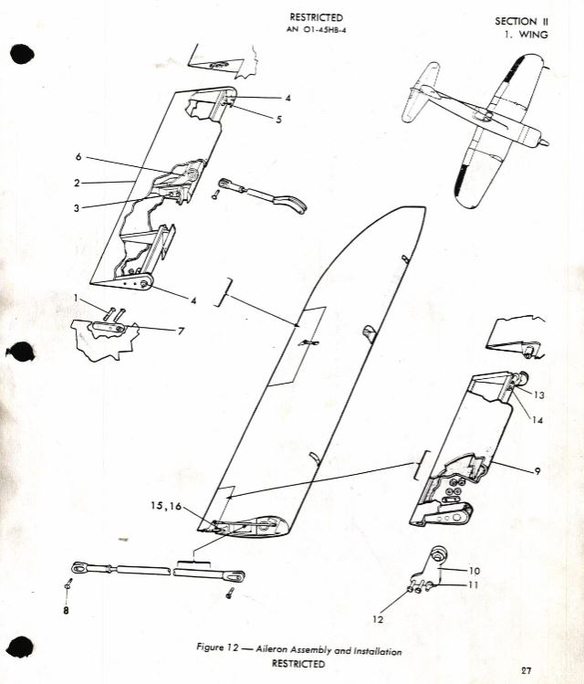
Simply put, the group assembly parts list contains exploded view illustrations of assemblies within an aircraft. Within each exploded view, individual parts are identified by numbers, and on the pages following each illustration, these numbers are listed with the corresponding part number for that item. Once you find a part number using the exploded view, you can search for that part number on the AirCorps Library site, and pull up the engineering drawing for that part or assembly! And of course once you find the drawing, you can learn the specifics about that part, such as dimensions and materials.
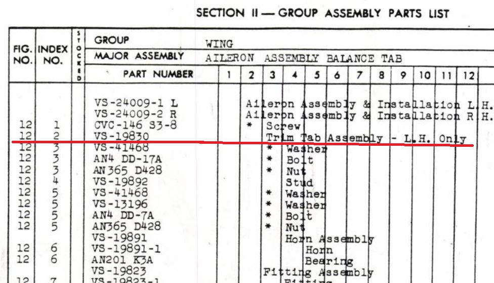
Taking an example from the F4U-4 parts catalog, the images below demonstrate how a standard illustrated parts catalog looks. The image on the left is the exploded view, in this case, of the Corsair aileron assembly. Note that individual components of the aileron are designated by a line that points to a number. Also note that this particular exploded view is labeled "Figure 12". The image to the right is found on the facing page next to the exploded view, and as you can see, lists the part numbers found within the aileron assembly. The column on the far left of this image indicates the figure number that these part numbers match with, in this case Figure 12. The next column is the "Index No". These Index numbers are the ones that correspond to the numbers pointing out specific parts in the exploded view drawing.
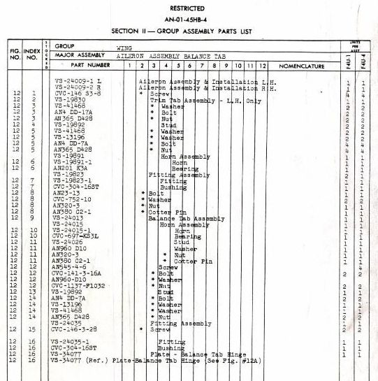
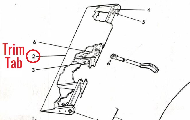
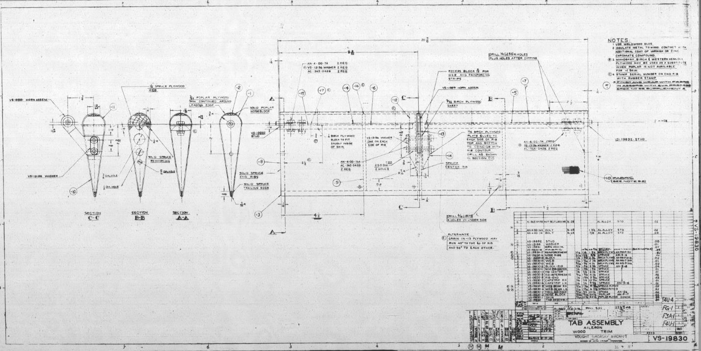
If we zoom in a bit on these drawings, it's easier to understand the connection between the exploded view and the parts list (or Bill of Materials). The number 2 points to the trim tab assembly in the exploded view, and if we reference figure 12, index number 2 on the parts list, we can confirm that by the description. We can also see that the part number for the trim tab assembly is VS-19830. After locating the part number, 19830, we can search for it on AirCorps Library, and find that drawing - which in this case just happens to have the overall dimensions for the trim tab! (third image)
Next Assembly - What You Need Isn't Always Where You Think It Should Be
Understanding how to use the “Next Assembly” or “Next Assy” portion of an engineering drawing can help you quickly find information you are looking for. Often small (but very important) pieces of data, such as overall dimensions will not be listed on a drawing that you are looking at. Finding this data requires you to “go up and down the ladder” of drawings - using the next assembly information. Going up and down the ladder is my personal way of thinking about the next assembly area of a drawing, and once you learn how to do it, it’s like riding a bike!
Let’s use a specific example:
Say you are looking at part drawing 192235 (below). This drawing gives dimensional data for the right hand mixture control lever assembly for the Lockheed P-38E Lightning. To “go up the ladder” and see where this lever gets installed in the next level assembly, we look just above the part number in the next assembly column. The part number listed as the next assembly for the control lever is 192236.
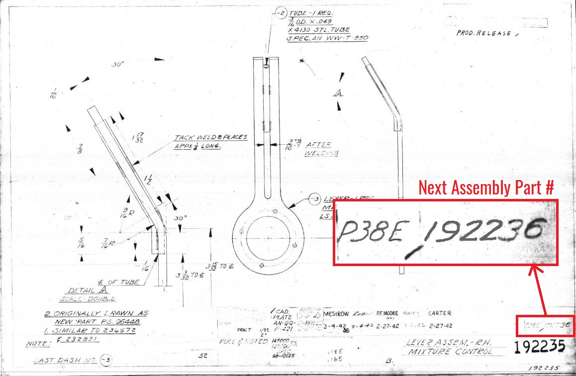
When we look at drawing 192236 (below), which is the drum assembly for the right hand mixture control, we can see where the lever 192235 (listed on the left) fits into this larger assembly, along with any additional parts that are part of this assembly.
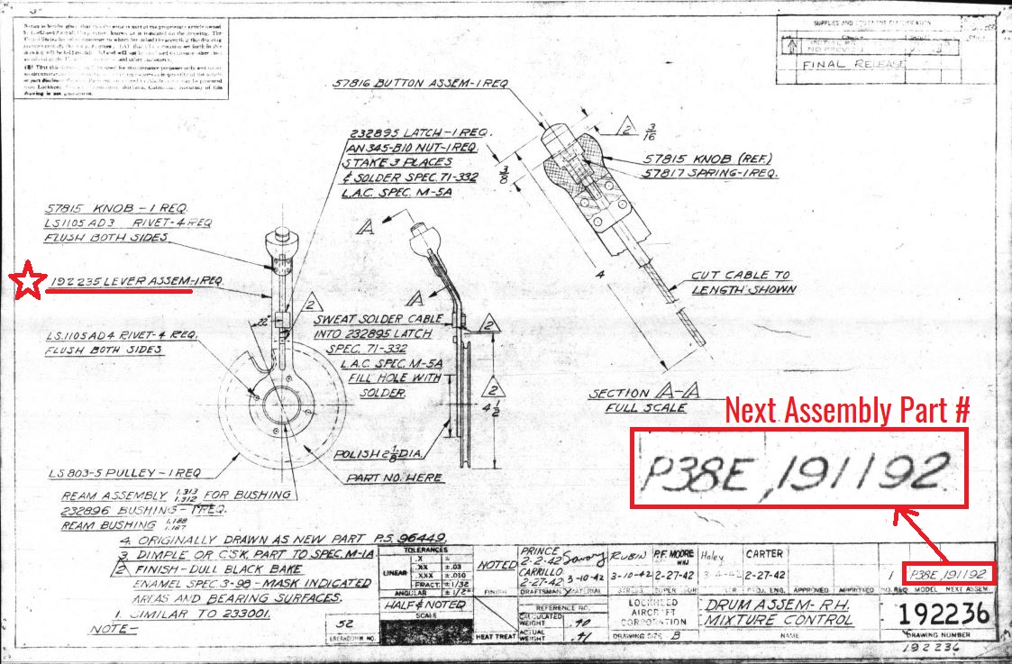
From there we can continue to move up the ladder to the next assembly drawing 191192 which is the stand assembly for all of the engine controls. In the detail image of drawing 191192 shown below, we can see the assembly that both of the drawings above fit into.
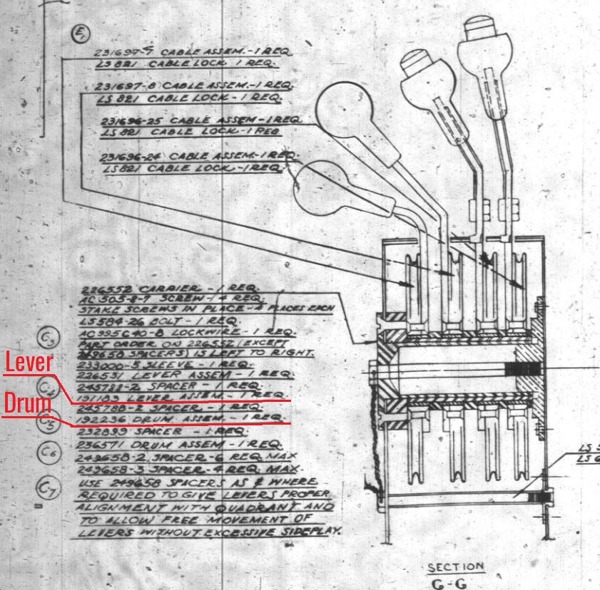
As a model builder, seeing these more complete assemblies is important, but dimensional data is always found on a more individual part basis. Looking in the notes sections next to larger assemblies (exactly like drawing 191192 to the left), it is common to see part number breakdowns of the components that make up the assembly. You can then use these part numbers to go “down the ladder” and find more specific information (such as dimensions) pertaining to individual parts.
In addition to the sometimes time consuming task of finding the drawing that contains the information you need, there is always the possibility that the drawing or part number you are looking for is unavailable. Manufacturers did not always include every individual drawing on a given set of microfilm, and because of this your part number search may come up with no results. If you search AirCorps Library for a part number and get a “no results” answer, it does not mean that we are withholding information, but simply that the drawing you are looking for was not included on the set of drawings that we currently have digitized. It is for this exact reason that we try to acquire and digitize multiple sets of microfilm for the same aircraft. Doing this often fills in gaps, and gives a much more complete selection of drawings.
Lofting and Contours
Contours and loft data (also called ordinates) is another topic that I receive many questions about. Whether you are building a full size airworthy aircraft or a scale model, understanding the loft lines for that aircraft is necessary for getting an accurate profile. However, loft information is often not contained (or only partially contained) on a set of microfilm for a given aircraft.
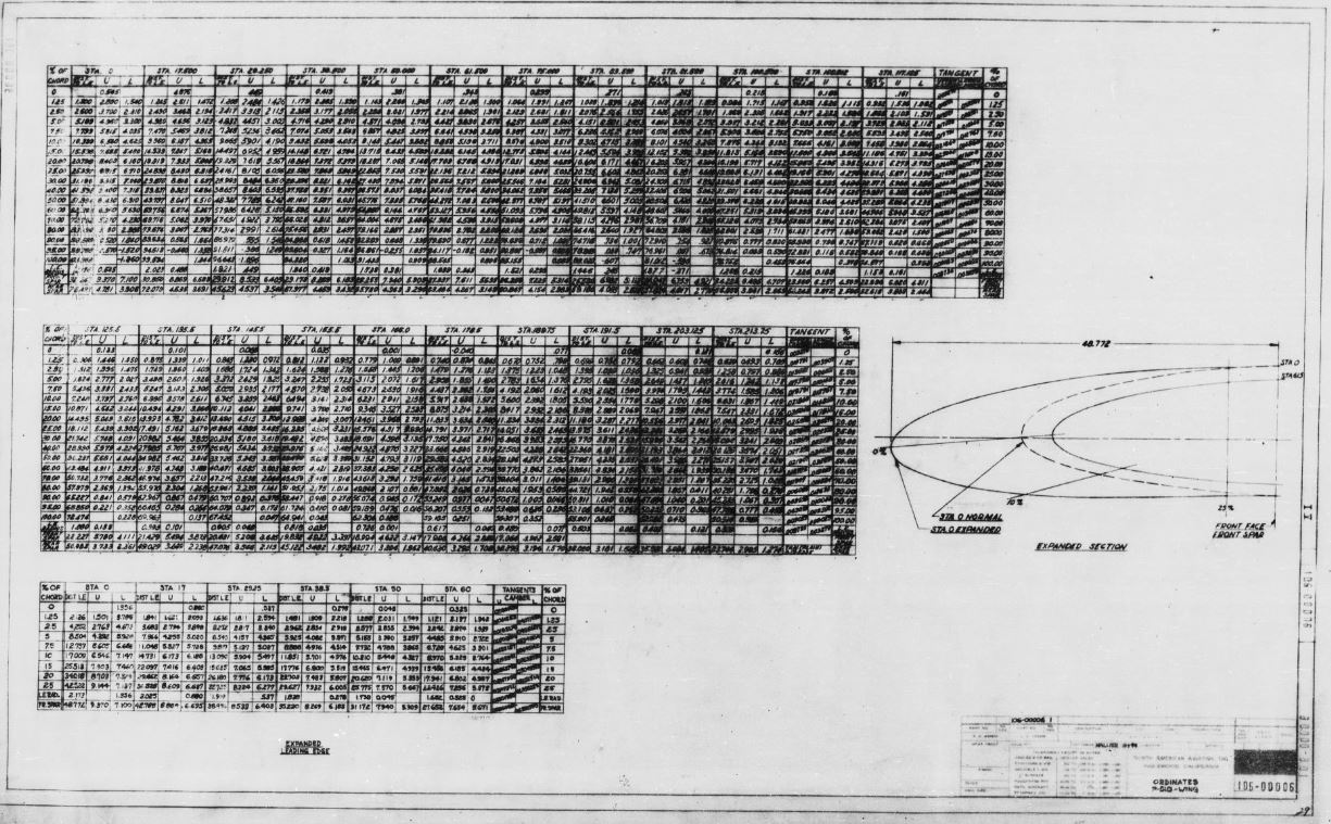
For example, there are several pages of ordinates info for the P-51D wing (drawing 106-00006), but the same information for the fuselage is nowhere to be found. For our restoration projects we actually 3D scanned an entire P-51D fuselage so that we could recreate the loft lines using the new data. My theory is that loft/ordinates were more highly classified because they would have been essential to the design and manufacturing process. If these drawings fell into the wrong hands during WWII, the enemy could have easily understood and stolen the design information behind the aircraft, and repurposed it.
That being said, there are plenty of aircraft manufacturers that did include contour and loft data on their microfilm along with the general part drawings. Searching the AirCorps Library website within a specific aircraft section for the terms “loft”, “contour”, or “ordinates” will quickly tell you if this information is available for the aircraft you are interested in.
Accuracy Is What You Make It!
As you can see, using the AirCorps Library website can be a bit of an information overload if you’re new to the world of incredibly detailed and scratch-built scale models. However, once you start to understand the system of how to move between drawings and gather the data you need, you can create a model that looks less like a model, and more like the real thing! Having an exhaustive amount of information at your fingertips allows you to get as detailed as time and money will allow, while still keeping the accuracy that most model builders crave.
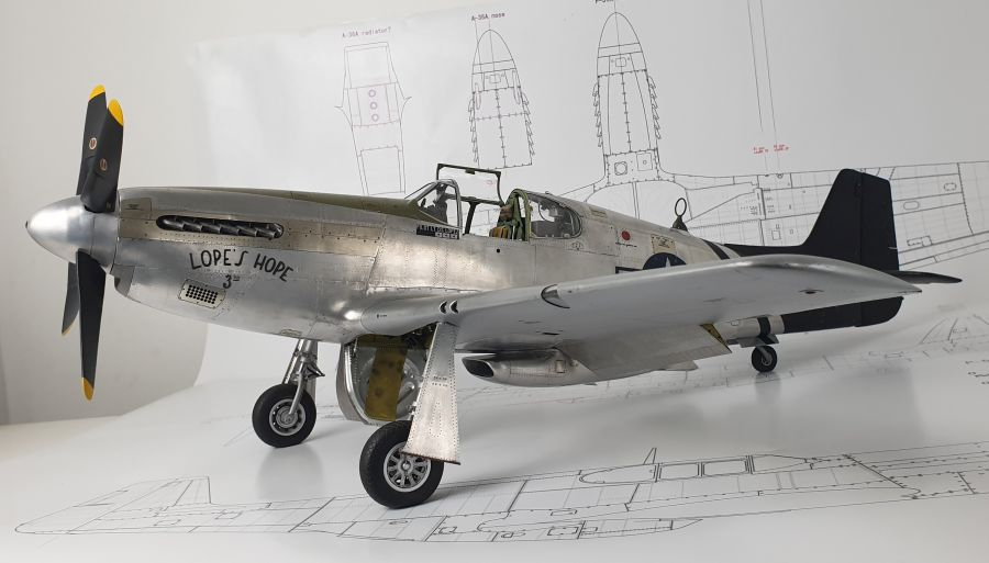
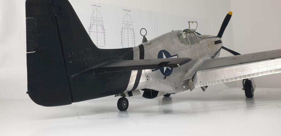
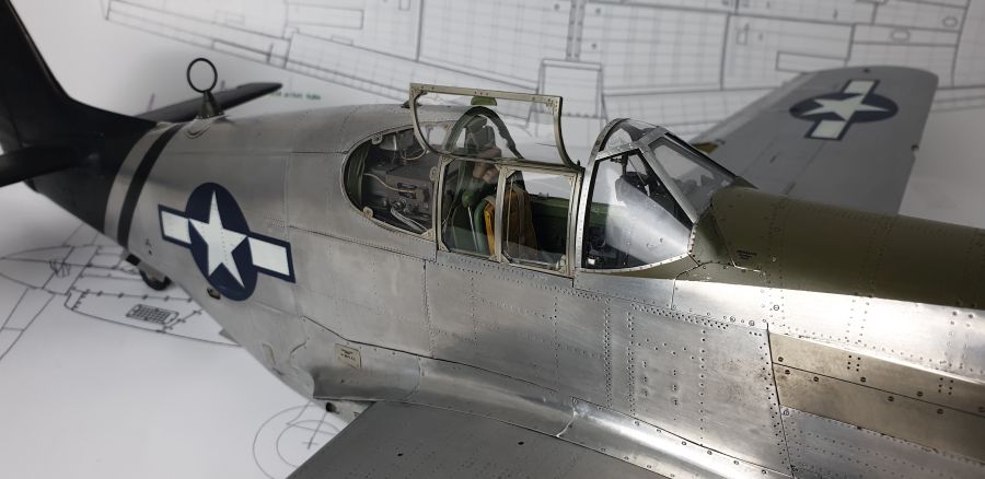
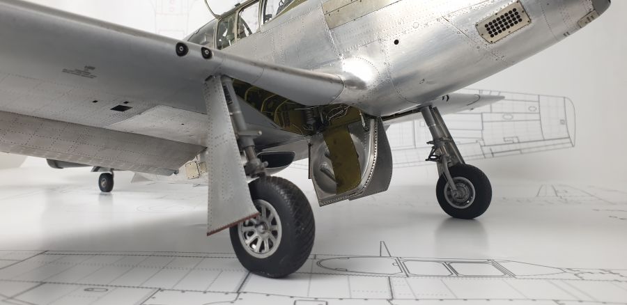
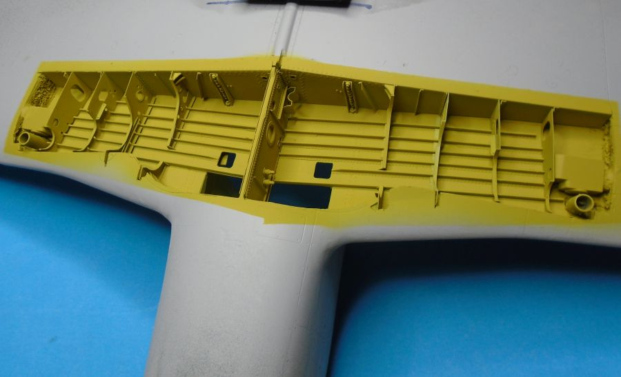
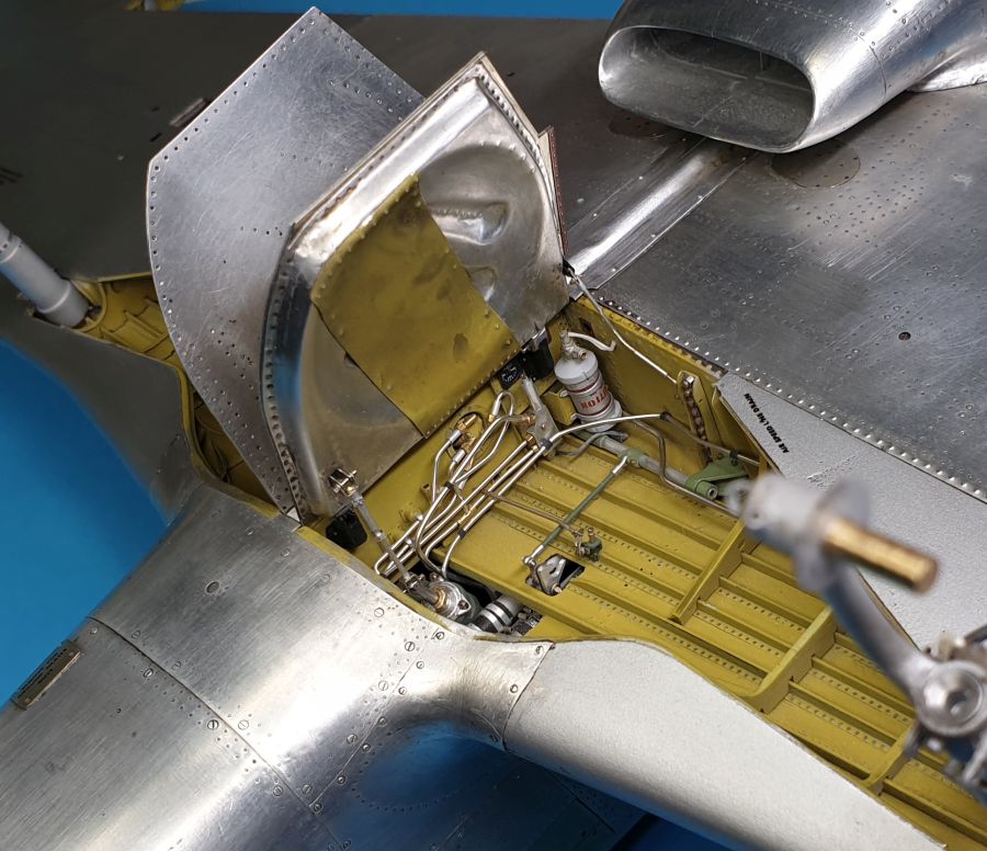
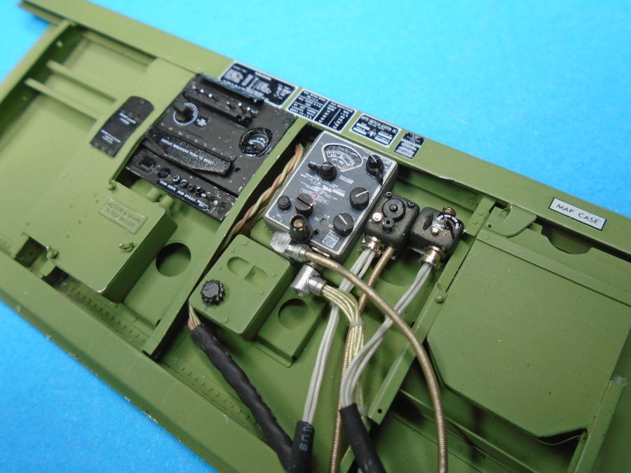
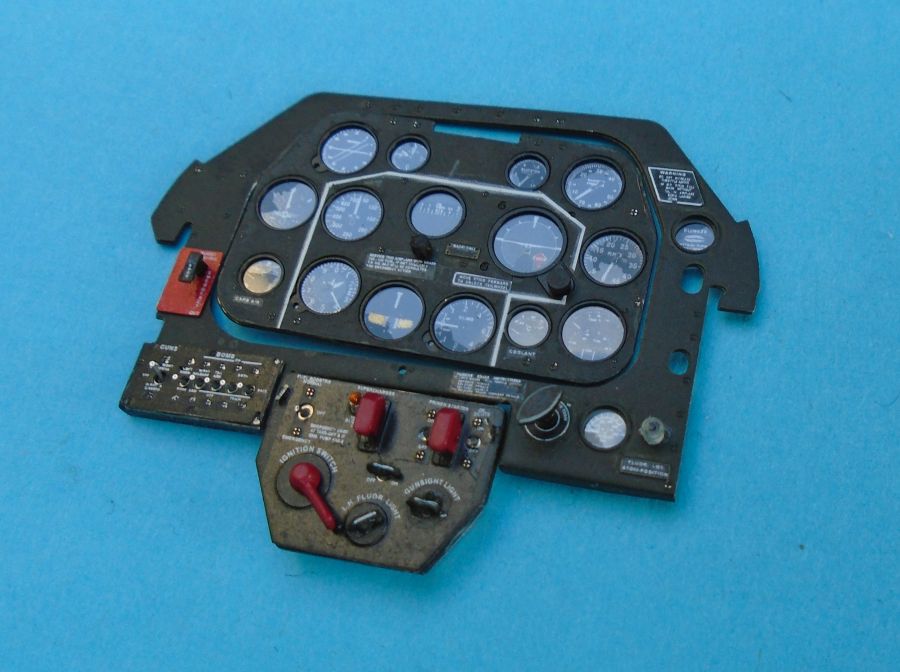
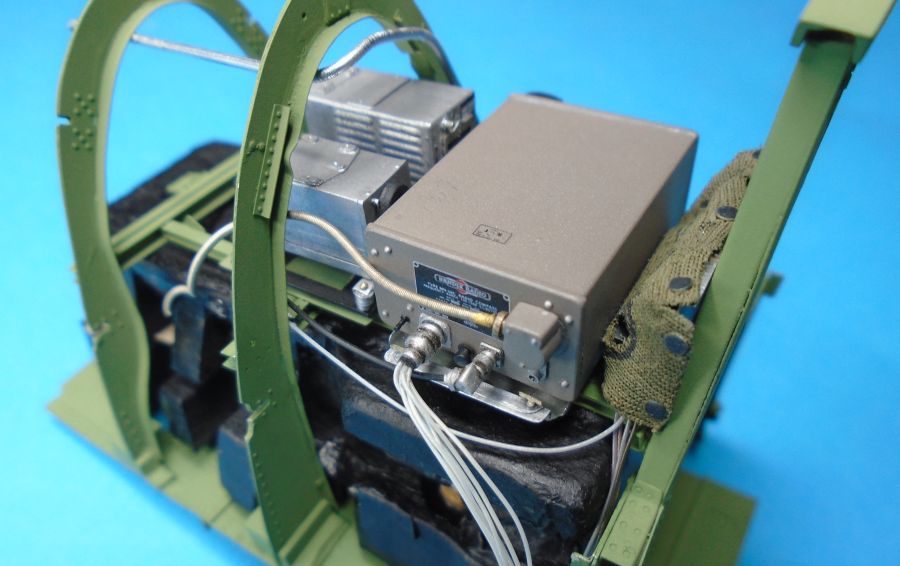
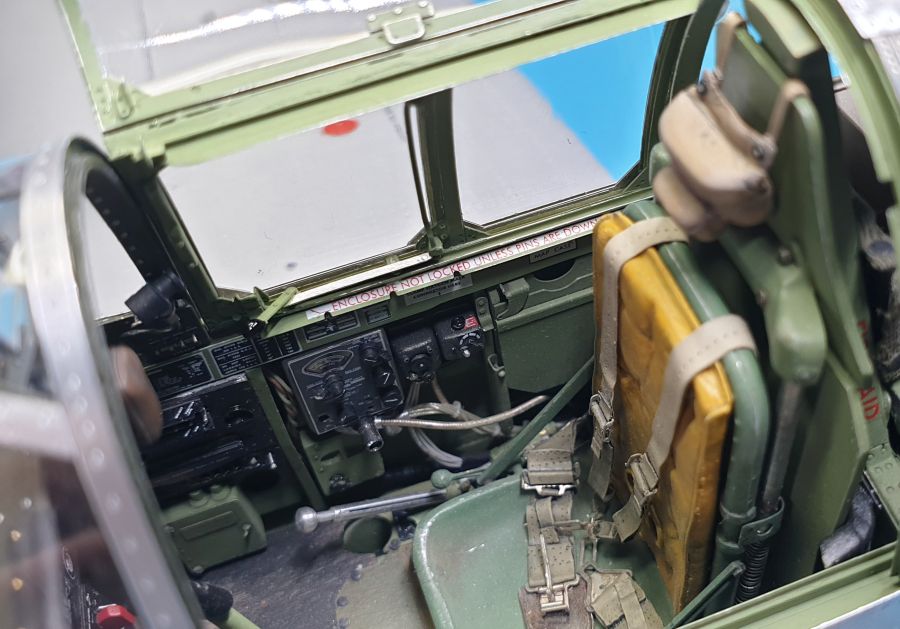
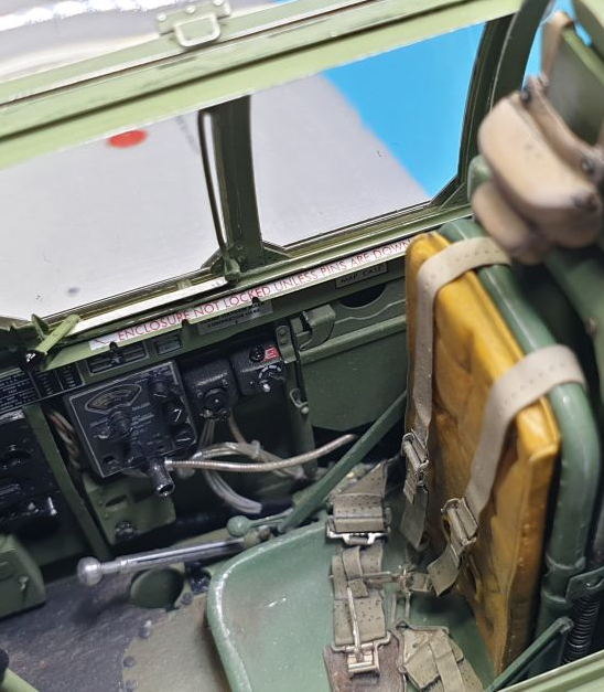
In closing, I’d like to share some photos of a 1/18 scale build that one of our AirCorps Library members finished several years ago. Some of you may be familiar with the work of Peter Castle out of the UK, but the work he did on his model of the P-51C, Lope’s Hope 3rd, is truly incredible. You might also know Peter as the founder of the website AirScale, which specializes in highly accurate cockpit and instrument panel components for warbird modelers. Peter's model is especially close to my heart because Lope’s Hope 3rd is a restoration completed here at AirCorps Aviation (the parent company of AirCorps Library). In some of the images below it can be hard to tell that Peter’s build is a work of miniature. For more photos and a full detail of Peter's build, see his forum postings in the works-in-progress area on the Large Scale Planes website.
As you can see, it takes an incredible amount of skill to create a model like this, but it also takes access to the right information.
If you are interested in becoming a member of AirCorps Library to help improve the accuracy of your warbird build, CLICK HERE to sign up today for just $9 per month or $75 per year! Remember, that this membership gets you full access to over 499,000 warbird engineering drawings and over 9,000 warbird technical manuals.
Happy building!
Just For Reference - Full Scale Lope's Hope 3rd at AirCorps Aviation:


Peter Castle's Lope's Hope 3rd Model: